
The Mittens Keyboard MKII
In the last post about building keyboards I talked about how easy it turned out to be to hand wire a keyboard, I’ve got a new one of the same design that I just finished. I thought I’d share that build log with you all.
Full disclosure, I’m writing this blog post on it.
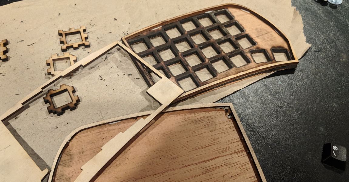
This time I decided to cut the pieces out of wood instead of out of plastic, it just looks a bit nicer. I also took the canvas keycaps off of the first version and put them on here because those keycaps look freak’n awesome with wood next to them.
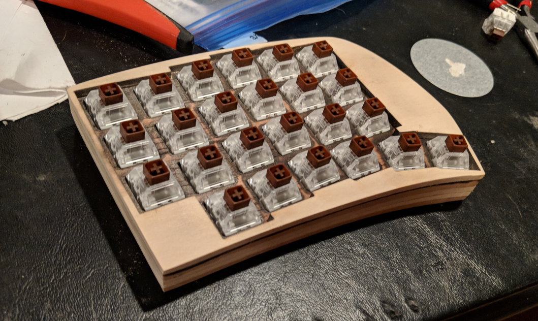
I also decided to give the Kaihua Kailh Box Browns a spin on this one. I tried them out while the board wasn’t done yet and decided they have a nice resistance to them. I also like the idea that spilling my coffee might not result in a keyboard that has to dry out.
Since I cut the case out of wood with a laser, I had to do a bit of sanding to get the sides to come out again. To make this easier I actually glued the case together first, then I clamped it to the workbench and got to sanding.
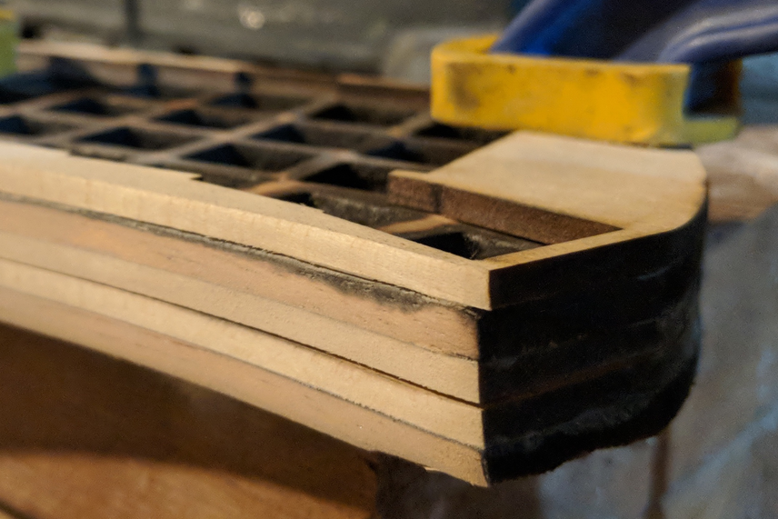
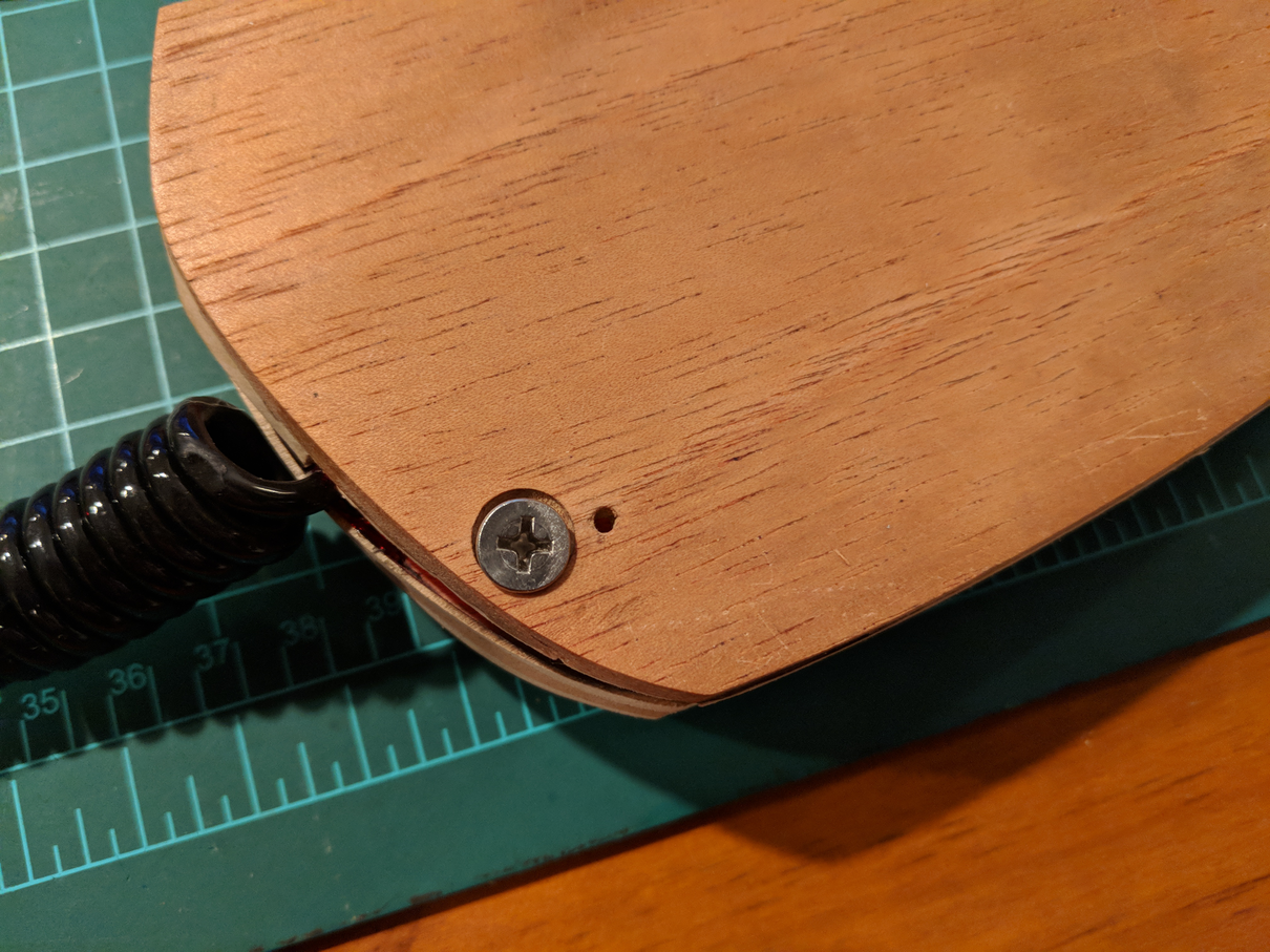
In order to keep the case together after I put things together, I decided to add little edges that would keep the sides in place, and then I countersunk a hole in the bottom of the case and added a tapped fitting into the wood on the inside. This worked okay, but I ended up having to clip the fitting a little in order to get it to fit inside the case.
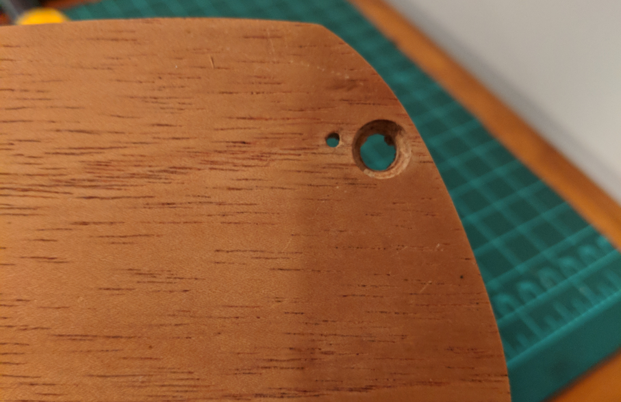
I used a stainless still screw to keep it in. For version 3, I plan to build this functionality into the design of the case so that I don’t have to retro fit it so strangely.
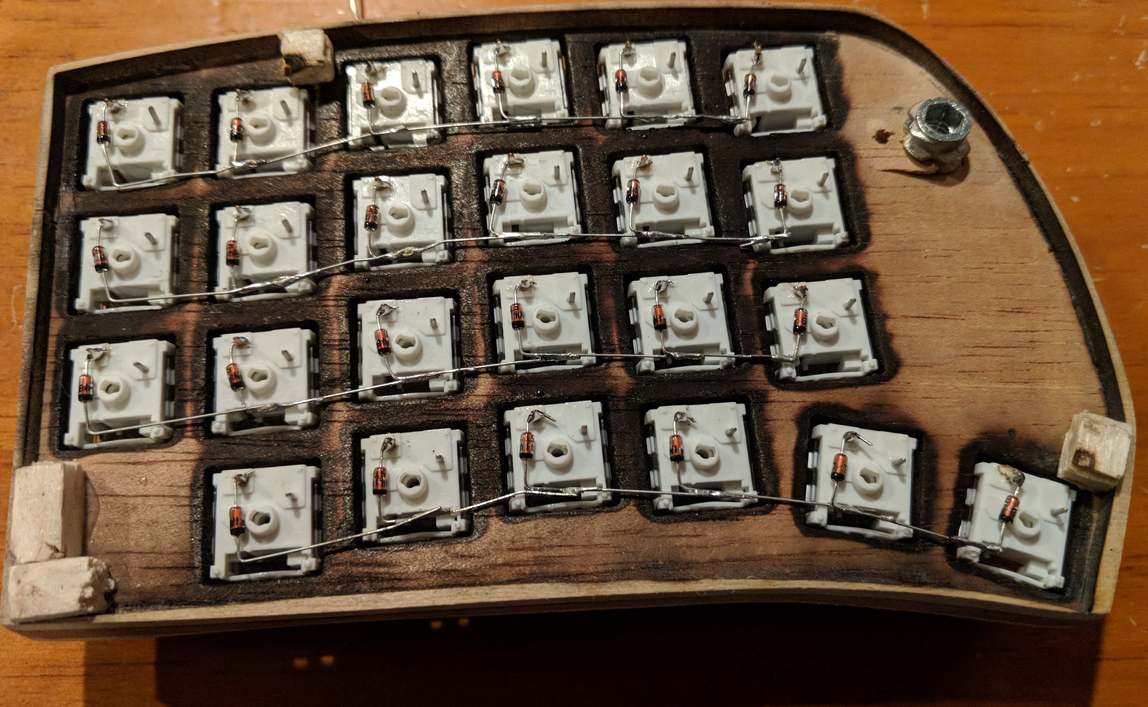
Once I had everything set up, I glued the key switches in with super glue. You could also use something like wood glue, or some sort of plastic cement. I would advise against using hot glue like I did in the first version of this because as the hot glue set, it would push the keys out of the holes in strange ways, so I ended up with some uneven keys. Not to say you can’t use hot glue for other stuff, hot glue is great.
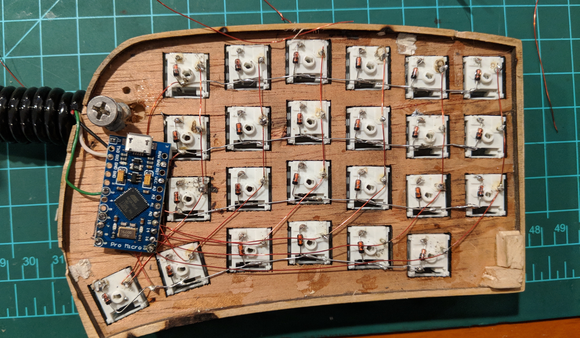
Once the switches were glued I wired up all of the rows using the diodes. You might also be able to do this with diodes in the columns, but I think the rows works a little bit neater.
Once you’ve got the rows soldered up, it’s time to attach the columns and also to add lead wires to the rows to go to your microcontroller. For this some people like hookup wire, the only problem with hookup wire is you have to plan it out really carefully, and if you mis-measure, you can pretty easily end up with contacts touching by accident. To avoid this, I recommend solderable enamel wire. I used a 28g PN155 wire from Remington Industries, it was fairly inexpensive on amazon and it showed up pretty fast.
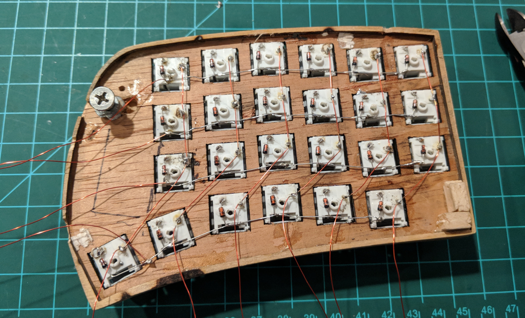
You might notice that I left a whole lot of wire on the end of that. This is on purpose for two reasons: 1 - solderable enamel wire is very cheap. Like, $10 for 500 ft. 2 - It meant that I didn’t have to do any planning about where stuff would get routed once I got it all together.
Next I added the microcontroller
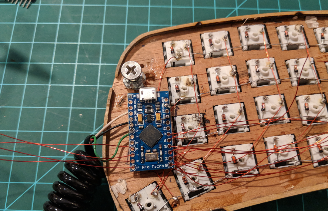
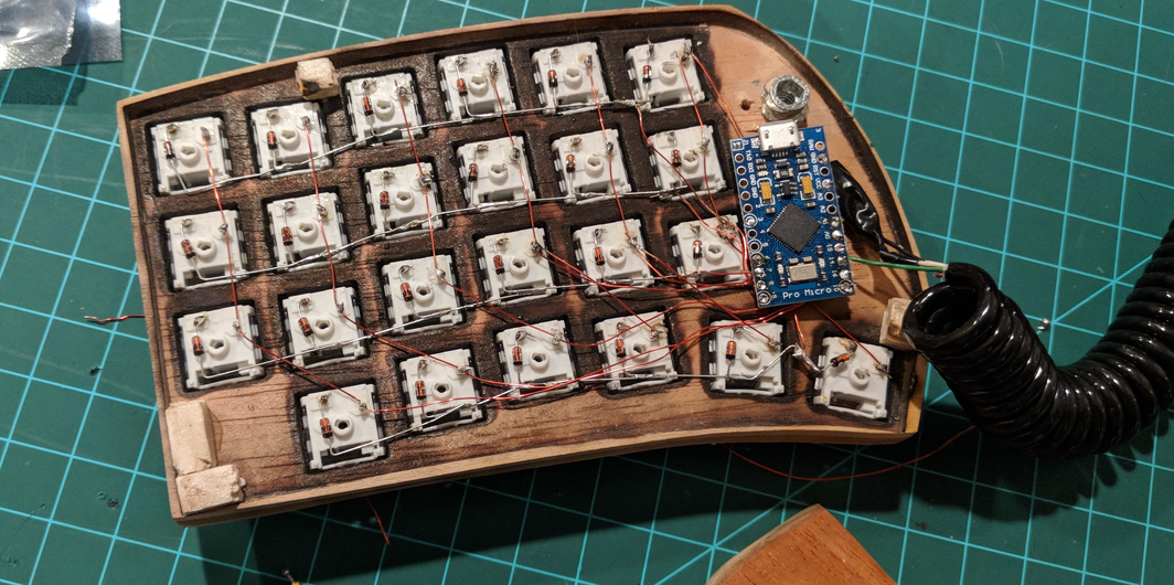
Once it’s fit it was just a matter of pulling the wires tight. After getting them tight and soldered to the microcontroller I did a quick sanity check to make sure all of the connections were good. I did this by taking my multimeter and just using the continuity checker to make sure all of the places I had soldered were connected and that it wasn’t connected to any of the columns. One of the hard parts about working with enamel wire is that you have to melt or burn off the enamel coating on all of the solder points. Once that was done I trimmed off the wire just above the microcontroller and glued it and the cables in place with hot glue.
After that it’s more or less just a matter of repeating the same process on the other half of the keyboard.
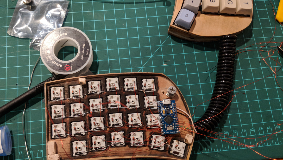
For those of you who look closely at that last one, you might notice that that half has a few weird wires going on. After I started soldering the microcontroller I realized that some of the wires had come loose and got pulled away from the pins they were supposed to be attached to. Rather than starting over I just added more wire and soldered it to the pins that were still good.
If you know your let’s split very well (or you read my last post about it), you might also notice that this is actually just a modified let’s split. It’s not! it also has all of the rows and columns backwards because I soldered the first one wrong and didn’t want to deal with it on the second one. :P
Anyway, that’s all of it! It really wasn’t too hard. If you’ve got basic soldering tools and access to a case or laser cutter (These are starting to show up all over the place, our library has one.), then you could build one yourself. I sourced and bought all of the parts for this keyboard for around $45-50 (not counting keycaps). You could probably do it for even less if you can find the right deals. I was at a goodwill the other day and there was a Monoprice keyboard with cherry blues in it on the shelf for $3. Anyway, what I’m saying is that keyboards don’t have to be an expensive hobby! I mean, they can be if you’re an idiot like me who drops $70 on a keycap set from massdrop at the drop of a hat, and feels like it was a good deal. This hobby with be the end of me.
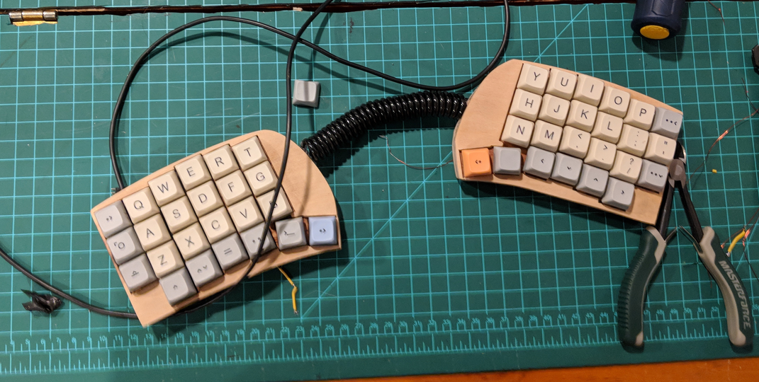
So this story makes it sound like this went off without a hitch. If you think that’s true, I will direct you to the following picture.
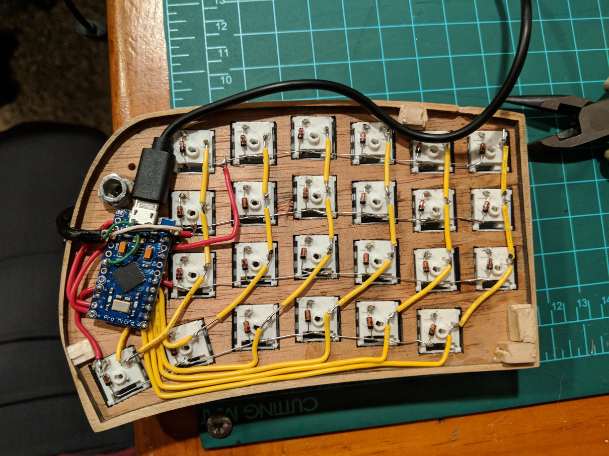
Look at that beautiful cable routing! It’s so fancy with it’s color coordinated cables and nice routing around the keys! There was just one problem, it didn’t work. I couldn’t get the microcontroller to flash correctly. So I took it all apart, plugged in the microcontroller by itself to see if I could flash it. It worked. Must be my wiring right?
So I wired it up again exactly the same way. Still didn’t work, what the heck! So I took it all apart and ordered some new arduino pro micros. I must have gotten a weird one right?
When I wired it up in the new one with the new wire, the first half worked perfectly! Yes, it must have been that arduino. Thats the only explanation. So I went to wire up the second half and again nothing worked! What the heck? This other one worked.
This is when I discovered there is such a thing as power only micro usb cables, and that I own one. Neat. Anyway, for future reference, always make sure that your cable works before you rip things apart and put them back together 3 times.